
NW725P
User Manual
V1.0
COPYRIGHT & TRADEMARKS
Specifications are subject to change without notice. NETCORE® is a registered trademark of NETCORE INDUSTRIAL CO.LTD.
Other brands and product names are trademarks or registered trademarks of their
respective holders.
No part of the specifications may be reproduced in any
form or by any means or used to make any derivative such as translation, or
adaptation without permission from NETCORE INDUSTRIAL CO.LTD. Copyright © 2009 NETCORE
INDUSTRIAL CO.LTD.
All reserved.
Certifications
FCC Part 15 Class A, CE.
Package Contents
The following items should be found in your package:
Ø One NW725P
Ø One DC 9v power adapter
Ø One QIG
Ø One CD
Please make sure that the package
contains the above items, if any of the listed items are damaged or missing,
please contact with your distributor.
Contents
1.3. Supporting
Standard and Protocol
2.3. Hardware
Installation Procedures
3.2. Additional
Settings for Wireless Client
3.3. Checking
PC’s IP and Connection with the Router..
1. Introduction
1.1. Product Overview
This NW725P is a cost-effective IP Sharing Router that enables multiple
users to share the Internet through an ADSL or cable modem. The NW725P is
embedded with a IEEE 802.11b/g/n access point that allows you to build up a
wireless LAN. With the support of new emerged 802.11n standard, the access
point provides data transfer of up to 300Mbps, up to 6 times faster than
1.2. Main Features
Ø
DHCP Client、PPPoE
Client、Static IP、PPTP Client、L2TP
Client
Ø
Support wireless mode: AP、Multi-AP(Multi-SSID)、WDS、AP+WDS、Repeater、Client
Ad-hoc、Client Infrastructure
Ø
Wireless security: Non、WEP、WPA
Personal、WPA2 Personal、WPA&WPA2 Personal、WPA
Enterprise、WPA2 Enterprise、WPA&WPA2
Enterprise、802.1x&WEP Radius
Ø
Turbo Mode
Ø
WMM
Ø
Ø
MAC Filter
Ø
IP Access Control
Ø
Time Based IP
Access Control
Ø
DNS Filter
Ø
Block WAN
Ø
QoS
Ø
Host Based
Bandwidth Limit
Ø
Application&Game
Based QoS
Ø Virtual Service
Ø DMZ
Ø Port Trigger
Ø
UPnP
Ø PPTP Pass-through
Ø L2TP Pass-through
Ø IPSec Pass-through
Ø User Setup(user
name&password)
Ø WEB Server Setup(web
remote access)
Ø
Time Zone(NTP)
1.3. Supporting Standard and Protocol
Ø IEEE 802.11b/g/n
Ø IEEE 802.11e
Ø IEEE 802.11h,
Ø IEEE 802.11k
Ø IEEE 802.11i
Ø IEEE 802.3 10Base-T
Ø
IEEE 802.3u 100Base-TX
1.4. Working Environment
Temperature
Ø 0° to 50° C (operating),
Ø -40° to 70° C (storage)
Humidity
Ø 10% to 90 % non-condensing
(operating),
Ø 5% to 90% non-condensing (storage)
Power
Ø DC 9V
2. Hardware Installation
2.1. System Requirement
Ø Broadband Internet Access Service(DSL/Cable/Ethernet)
Ø 10/100Base-T Ethernet card and TCP/IP protocol
installed for each PC
Ø Internet Explorer 5.0 or higher for Web configuration
Ø
802.11n ,
2.2. Panel
Front panel
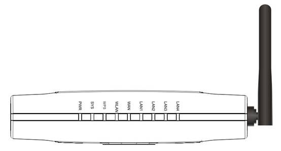
Figure 2‑1
|
LED |
Function |
|
|
PWR |
ON |
Power on |
|
Off |
Power off |
|
|
SYS |
ON and Off |
Abnormal |
|
Flashing |
|
|
|
WPS |
Flashing slowly |
WPS is running |
|
OFF |
WPS is not running |
|
|
WLAN |
Flashing |
Wireless data
transmitting |
|
Off |
Wireless off |
|
|
WAN |
On |
WAN Connection normal |
|
Flashing |
Data transmitting |
|
|
Off |
WAN Connection abnormal |
|
|
LAN |
On |
LAN Connection normal |
|
Flashing |
Data transmitting |
|
|
Off |
LAN Connection abnormal |
|
Rear panel
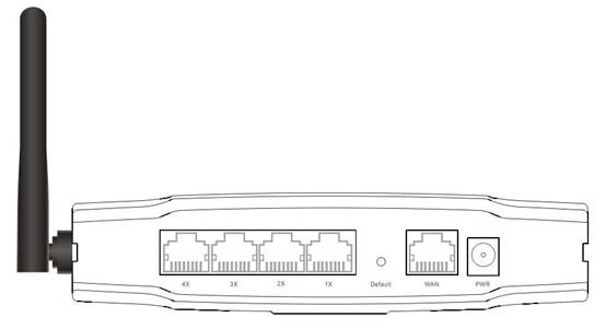
Figure 2‑2
|
Number |
Description |
Function |
|
1 |
PWR port |
Connect to Power adapter, please don’t use the unknown power adapter, otherwise your device may be damaged. |
|
2 |
LAN port |
Connect with computer NIC or Ethernet device |
|
3 |
WAN port |
Internet access |
|
4 |
Default |
Restore settings, please press the button for about 10 seconds, it will restore settings to the factory configuration |
|
5 |
Antenna |
|
2.3. Hardware Installation Procedures
The procedures to install the NW725P please
refer to Figure
2‑3.
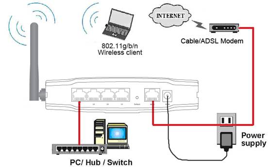
Figure 2‑3
Ø Step 1 connecting your computer to
the LAN port.
Attach one end of the Ethernet cable with RJ-45 connector to
your hub, switch or a computer’s Ethernet port, and the other end to one of the
LAN ports of your NW725P.
Ø Step 2 Connecting Cable/ADSL Modem to
the WAN port.
Connect the Ethernet cable attaching to your Cable/ADSL modem
to the WAN port of your NW725P.
Ø Step 3 connecting the power adapter.
Connect the single DC output connector of the power adapter
to the power jack on the side of the NW725P. Then plug the Power Adapter into an
AC outlet.
Ø Step 4 Power on the following devices
in this order:
Cable/ADSL modem, Router, and PCs
3. Login
You can manage the NW725P through the Web browser-based configuration
utility. To configure the device via Web browser, at least one properly
configured computer must be connected to the device via Ethernet or wireless
network. The NW725P is configured with the default IP address of
192.168.1.1 and subnet mask of 255.255.255.0 and its DHCP server is
enabled by default. Before setting up the Router, make sure your PCs are
configured to obtain an IP address automatically from the Router by the steps
below.
3.1. Configure computer
3.1.1. Windows 98/Me
1. Go to Start à Settings à Control
Panel.
2. Find and double-click the Network icon. The Network dialog
box appears.
3. Click the Configuration label and ensure that you have
network card.
4. Select TCP/IP. If TCP/IP appears more than once, please
select the item that has an arrow “à” pointing to the network card
installed on your computer. DO NOT choose the instance of TCP/IP with the words
“Dial Up Adapter” beside it.
5. Click Properties. The TCP/IP Properties dialog box
appears.
6. Ensure the Obtain IP Address Automatically is checked.
7. From the WINS Configuration dialog box, Ensure that
Disable WINS Resolution is checked.
8. From the Gateway dialog box, remove all entries from the
Installed gateways by selecting them and clicking Remove.
9. From the DNS Configuration dialog box, remove all entries
from the DNS Server Search Order box by selecting them and clicking Remove.
Remove all entries from the Domain Suffix Search Order box by selecting them
and clicking Remove. Click Disable DNS.
10. Click OK, back to Network Configuration dialog box
11. Click OK, if prompted to restart, click YES.
3.1.2. Windows 2000
Please follow the steps below
to setup your computer:
1. Go to Start à Settings à Control Panel
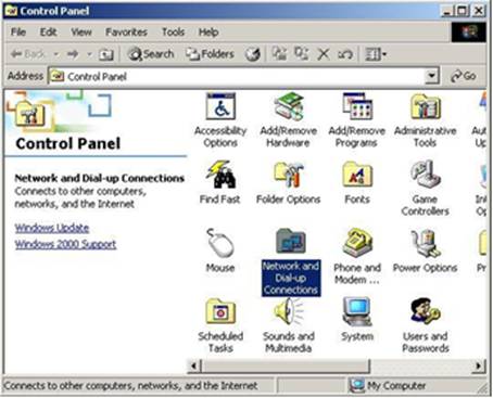
Figure 3‑1
2. Double click the icon
Network and Dial-up Connections
3. Highlight the icon Local Area Connection, right click your mouse, and click Properties
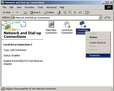
Figure 3‑2
4. Highlight Internet
Protocol (TCP/IP), and then press Properties button
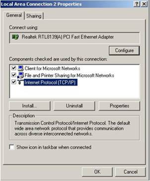
Figure 3‑3
5. Choose Obtain an IP
address automatically and Obtain DNS server address automatically, and then
press OK to close the Internet Protocol (TCP/IP) Properties window
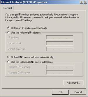
Figure 3‑4
6. Press OK to close the
Local Area Connection Properties window
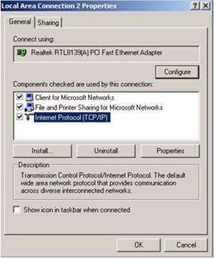
Figure 3‑5
3.1.3. Windows XP
Please follow the steps below
to setup your computer:
1. Go to Start à Settings à Control Panel
2. Click Network and Internet Connections
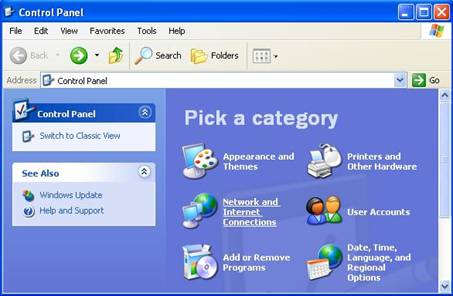
Figure 3‑6
3. Click Network Connections
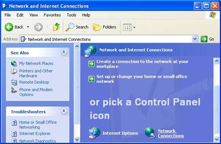
Figure 3‑7
4. Highlight the icon Local
Area Connection, right click your mouse, and click Properties
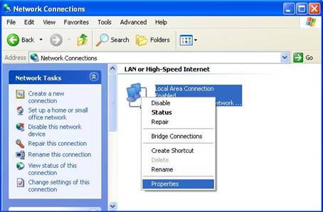
Figure 3‑8
5. Highlight Internet Protocol (TCP/IP), and then press Properties button
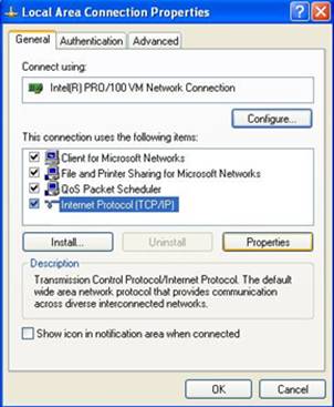
Figure 3‑9
6. Choose Obtain an IP address automatically and Obtain DNS server address automatically, and then press OK to close the Internet Protocol (TCP/IP) Properties window
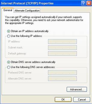
Figure 3‑10
7. Press OK to close the Local Area Connection Properties window
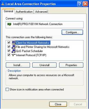
Figure 3‑11
3.1.4.
Windows Vista
Please follow the steps below
to setup your computer:
1. Go to Start à Settings à Control Panel
2. Click Network and Sharing
Center
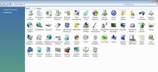
Figure 3‑12
3. Click Manage Network
Connections
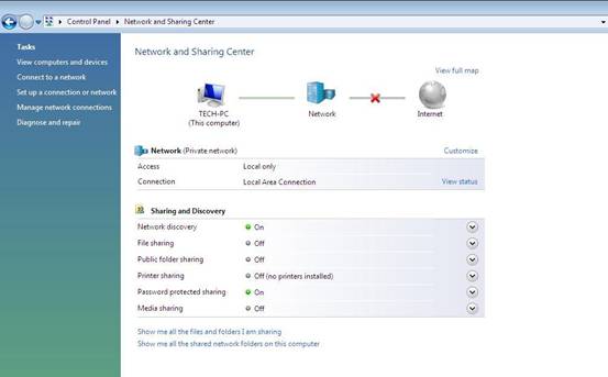
Figure 3‑13
4. Highlight the icon Local
Area Connection, right click your mouse, and click Properties
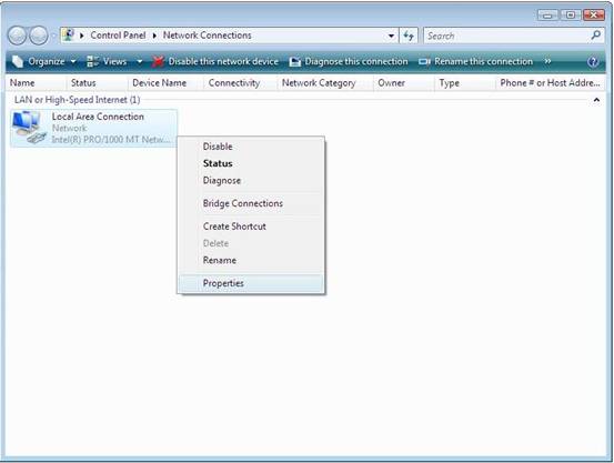
Figure 3‑14
5. Highlight Internet
Protocol Version 4 (TCP/IP) and then press Properties button
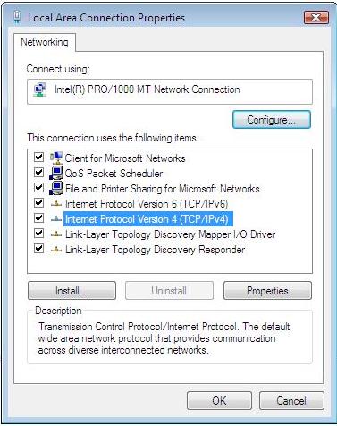
Figure 3‑15
6. Choose Obtain an IP
address automatically and Obtain DNS server address automatically, and then
press OK to close the Internet Protocol (TCP/IP) Properties window
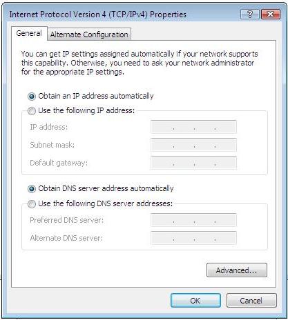
Figure 3‑16
7. Press OK to close the
Local Area Connection Properties window
Figure 3‑17
3.2. Additional Settings for Wireless Client
If you choose to access the router via a wireless client, also verify the
following:
1. Make sure your PC is equipped with 802.11b
2. Set the wireless adapter to use appropriate TCP/IP settings as
described in previous section.
3. Launch the wireless adapter’s provided utility and verify that your
wireless client is configured with these settings:
l Operation Mode: Infrastructure
l SSID: default
l Authentication: Disabled
l Encryption: Off
l Radio Band: 802.11B/G/N
3.3. Checking PC’s IP and Connection with the Router
After
configuring the TCP/IP protocol, use the ping command to verify if the computer
can communicate with the Router. To execute the ping command, open the DOS
window and
ping the
IP address of the NW725P at the DOS prompt:
l
For Windows
98/Me: Start -> Run. Type command and click OK.
l
For
Windows 2000/XP: Start -> Run. Type cmd and click OK.
At the DOS
prompt, type the following command:
If the
Command window returns something similar to the following:
|
C:\Documents and
Settings\admin>ping 192.168.1.1 Pinging 192.168.1.1
with 32 bytes of data: Reply from
192.168.1.1: bytes=32 time=1ms TTL=64 Reply from
192.168.1.1: bytes=32 time=1ms TTL=64 Reply from
192.168.1.1: bytes=32 time=1ms TTL=64 Reply from
192.168.1.1: bytes=32 time=1ms TTL=64 Ping statistics for
192.168.1.1: Packets: Sent = 4,
Received = 4, Lost = 0 (0% loss), Approximate round
trip times in milli-seconds: Minimum
= 1ms, Maximum = 1ms, Average = 1ms |
Then the connection
between the router and your computer has been successfully established.
If the computer fails
to connect to the router, the Command window will return the following:
|
C:\Documents and
Settings\admin>ping 192.168.1.1 Pinging 192.168.1.1
with 32 bytes of data: Request timed out. Request timed out. Request timed out. Request timed out. Ping statistics for
192.168.1.1: Packets:
Sent = 4, Received = 0, Lost = 4 (100% loss), |
Verify your computer's network settings are correct
and check the cable connection between the router and the computer.
In order to make the whole network operate successfully, it is necessary to configure the NW725P through your computer has a WEB browser installed. Please follow up the steps listed below.
3.4. Login
1.Startup
Internet Explorer,and
enter http://192.168.1.1, then press Enter
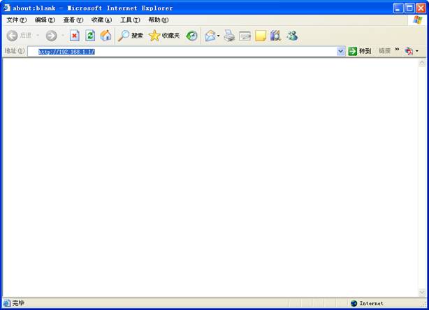
Figure 3‑18
2. After
successful login, you will be able to see the NW725P’s web-based configuration utility
refer to Figure
3‑19. From now on the NW725P acts as a Web server sending HTML
pages/forms at your request. You can click the menu options at the left to
start the configuration task.
In the home page of the NW725P, the left navigation bar shows the main options to configure the system. In the right navigation screen is the summary of system status for viewing the configurations.
Figure
3‑20
4. System configuration
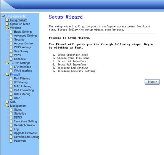
4.1. Setup Wizard
The setup wizard will guide you to configure access point for
first time. Please follow the setup wizard step by step.
1.
Click Next
Figure 4‑1
2.
Select one operation mode, then click
Next
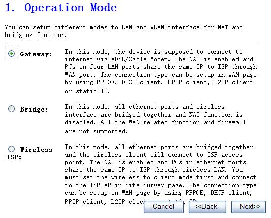
Figure 4‑2
Ø Gateway
In this mode, the device is supposed
to connect to internet via ADSL/Cable Modem. The NAT is enabled and PCs in four
LAN ports share the same IP to ISP through WAN port. The connection type can be
setup in WAN page by using PPPOE, DHCP client, PPTP client or static IP.
Ø Bridge
In this mode, all Ethernet ports and
wireless interface are bridged together and NAT function is disabled. All the
WAN related function and firewall are not supported.
Ø Wireless ISP
In this mode, all Ethernet ports are
bridged together and the wireless client will connect to ISP access point. The
NAT is enabled and PCs in Ethernet ports share the same IP to ISP through
wireless LAN. You must set the wireless to client mode first and connect to the
ISP AP in Site-Survey page. The connection type can be setup in WAN page by
using PPPOE, DHCP client, PPTP client or static IP.
3.
Time zone setting, click Next when
finished
The Time Zone allows your router to base its time on the settings configured here, this will affect functions such as Log entries and Firewall settings.
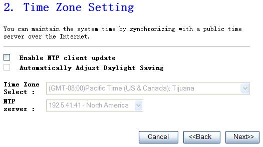
Figure 4‑3
Ø
Time Zone Select
Select the time zone of the country
you are currently in. The router will set its time based on your selection.
Ø
NTP Server
Address
You can manually assign time server
address if the default time server dose not works.
4.
Accomplish LAN setup then click Next
The
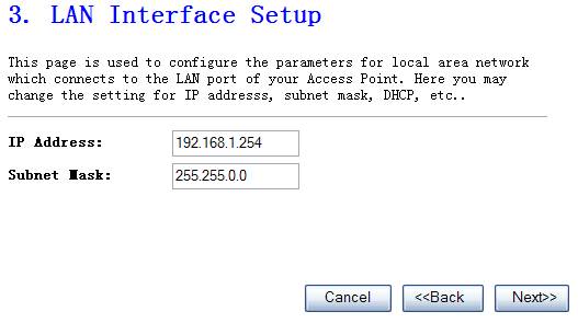
Figure 4‑4
Ø
IP Address
This is the router’s LAN port IP
address (Your LAN clients default gateway IP address),the default is 192.168.1.1.
Ø
Subnet Mask
Specify a Subnet Mask for your LAN
segment, the default is 255.255.255.0
5.
WAN Interface Setup
Use the WAN Settings screen if you have already configured the Quick Setup Wizard section and you would like to change your Internet connection type. The WAN Settings screen allows to specify the type of WAN port connect you want to establish with your ISP. The WAN settings offer the following selections for the router’s WAN port, Static IP, PPPoE, PPTP and DHCP Client.
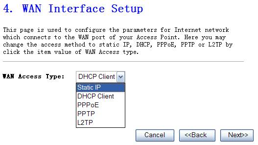
Figure 4‑5
Ø
Static IP address
Select Static IP if all the internet
port’s IP information is provided by your ISP. You will need to enter the IP
address ,subnet mask, gateway address ,and the DNS address provided to you by
your ISP.
Ø
DHCP Client
Select DHCP Client if Your ISP does
not give you any IP number and uername&password to use, this option is
commonly used for cable modem services.
Ø
PPPoE
Choose PPPoE(point to point over
ethernet) if Your ISP requires PPPoE connection, and you must enter the
username and password which your ISP provide.
Ø
PPTP
Your ISP requires you to use a PPTP
connection. Your ISP will provide you with a username and password. This option
is typically used for DSL services.
Ø
L2TP
Your ISP requires you to use a L2TP connection. Your ISP will provide you with a username and password. This option is typically used for DSL services.
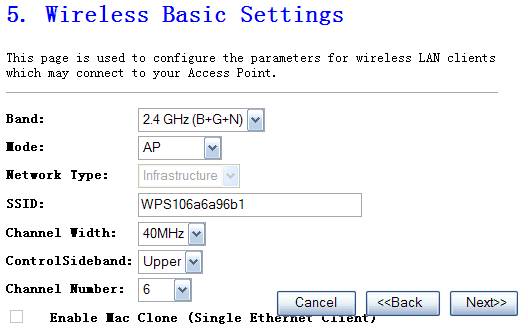
Figure 4‑6
Ø
Mode
It
allows you to set the AP to AP, Client, WDS or AP+WDS mode. The default is AP.
Ø
Network Type
There
are two type, infrastructure and hoc, the default is infrastructure
Ø
SSID
This
is the name of the wireless LAN. All the devices in the same wireless LAN
should have the same SSID, the default is default.
Ø
Channel Number
The
channel used by the wireless LAN. All devices in the same wireless LAN should
use the same channel.
7.
Wireless Security Setup
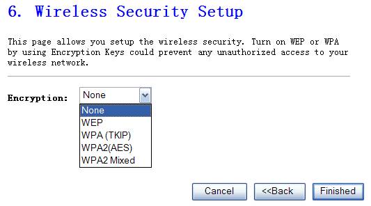
Figure 4‑7
Ø
Encryption Mode
This
NW725P supplies five different encryption modes.
Ø
None
Means
do not encrypt wireless data.
Ø
WEP
There
are two basic levels of WEP encryption, 64 bits and 128 bits, the more bits
password have, the better security wireless network is, at the same time the
speed of wireless is more slower. If you select WEP to encrypt your data,
choose the bits of password, it should be 64 bits or 128 bits. Then choose the
format of password; it should be HEX or ASCII. The valid character for HEX
format should be numbers from 0 to 9 or letters from A to F.
HEX
doesn’t support mixed letter and number mode. And ASCII supports mixed both
letters and numbers. By default, router provides four fields to input four
groups of password, you can input all of them or only one of them, and the client‘s
password only need to match one group of password.
This
is the name of the wireless LAN. All the devices in the same wireless LAN
should have the same SSID
Ø
WPA (TKIP)
TKIP
means “Temporal Key Integrity Protocol”, which incorporates Message Integrity
Code (MIC) to provide protection against hackers. Choose “Pre-Shared Key
Format”
Ø
WPA2(AES)
This use CCMP protocol to change encryption
key frequently. AES can provide high level encryption to enhance the wireless
LAN security.
Ø
WPA2 Mixed
This will use TKIP or AES based on the other communication peer automatically.
4.2. Operation Mode
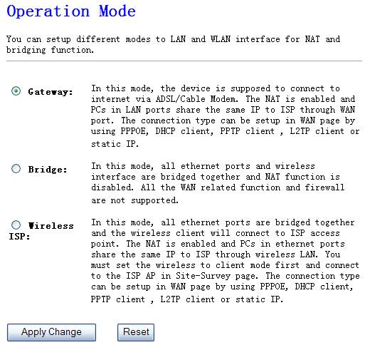
Figure 4‑8
Ø Gateway
In this mode, the device is supposed to connect to internet via
ADSL/Cable Modem. The NAT is enabled and PCs in four LAN ports share the same
IP to ISP through WAN port. The connection type can be setup in WAN page by
using PPPOE, DHCP client, PPTP client or static IP.
Ø Bridge
In this mode, all Ethernet ports and wireless interface are bridged
together and NAT function is disabled. All the WAN related function and
firewall are not supported.
Ø Wireless ISP
In this mode, all Ethernet ports are bridged together and the wireless client will connect to ISP access point. The NAT is enabled and PCs in Ethernet ports share the same IP to ISP through wireless LAN. You must set the wireless to client mode first and connect to the ISP AP in Site-Survey page. The connection type can be setup in WAN page by using PPPOE, DHCP client, PPTP client or static IP.
4.3.
Wireless
The
NW725P supplies the function of act as two AP simultaneously, but because the
difference of privilege, besides normal function of AP, the primary AP also has
extra function for some advanced settings and right management. So here you can
manage and configure your primary AP.
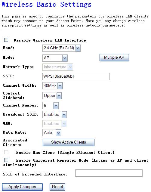
Figure 4‑9
Ø
Mode
It
allows you to set the Wireless AP to AP, Client, WDS or AP+WDS mode. The
default is AP mode.
Ø
Band
It
allows you to set the AP fix at 802.11b
Ø
Network Type
There
are two type, infrastructure and hoc, the default is infrastructure
Ø
SSID
This
is the name of the wireless LAN. All the devices in the same wireless LAN
should have the same SSID, the default SSID is 802.11bgn-SSID.
Ø
Channel Number
The
channel used by the wireless LAN. All devices in the same wireless LAN should use
the same channel.
Ø
Associated
Clients
Click
“Show Active Clients” button, then an “Active Wireless Client Table” will pop
up. You can see the status of all active wireless stations that are connecting
to the access point.
Ø
Enable Mac Clone
Click
the “Enable MAC Clone” button will copy the MAC address of your PC, which you
are using to configure the AP, to the WLAN MAC.
Ø
Enable Universal Repeater
Mode
To Enable Universal Repeater Mode, Acting as AP and client simultaneously
You
can set advanced wireless LAN parameters of this router. The parameters include
Authentication Type, Fragment Threshold, RTS Threshold, Beacon Interval, and
Preamble Type. You should not change these parameters unless you know what
effect the changes will have on this router.
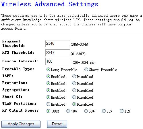
Figure 4‑10
Ø
Fragment
Threshold
"Fragment Threshold" specifies the maximum size of
packet during the fragmentation of data to be transmitted.
Ø
RTS Threshold
When the packet size is smaller the RTS threshold, the NW725P will
not use the RTS/CTS mechanism to send this packet.
Ø
Beacon Interval
The interval time of this NW725P broadcast a beacon. Beacon is
used to synchronize the wireless network.
Ø
Preamble Type
The “Long Preamble” can provide better wireless LAN compatibility
while the “Short Preamble” can provide better wireless LAN performance
Ø
IAPP
If you enable “IAPP”, it will allow wireless station roaming
between IAPP enabled access points within the same wireless LAN.
Ø
Protection
This is also called CTS Protection. It is recommended to enable
the protection mechanism. This mechanism can decrease the rate of data
collision between
Ø
WLAN Partition
Ø
RF Output Power
This option is 100% by default,you’d better not change this value because
of it will degrade the wireless transmit power.
This
Access Point provides complete wireless LAN security, include WEP, WPA (TKIP),
WPA2 (AES), WPA2 Mixed. With these security functions, you can prevent your
wireless LAN from illegal access. Please make sure your wireless stations use
the same security function.
4.3.3.1.
None
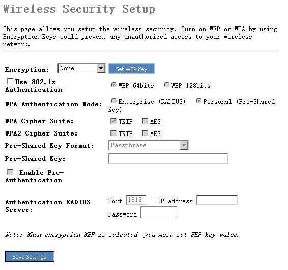
4.3.3.2.
WEP
When you select 64-bit or128-bit WEP
key, you have to enter WEP keys to encrypt data. You can generate the key by
yourself and enter it. You can enter four WEP keys and select one of them as
default key. Then the router can receive any packets encrypted by one of the
four keys
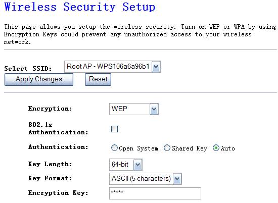
Figure 4‑11
Ø
Authentication
There are three authentication modes of WEP
Encryption, please select one or default.
Ø
Key Length
You can select the WEP key length for encryption, 64-bit or
128-bit. Larger WEP key length will provide higher level of security, but the
throughput will be lower.
Ø
Key Format
You may to select ASCII Characters (alphanumeric format) or
Hexadecimal Digits (in the "A-F", "a-f" and "0-9"
range) to be the WEP Key. < For
example: ASCII Characters: guest; Hexadecimal Digits: 12345abcde >
Click “Apply
Changes” at the bottom of the screen to save the above configurations. You can
now configure other advance sections or start using the router (with the
advance settings in place)
4.3.3.3.
802.1x&WEP
IEEE
802.1x is an authentication protocol. Every user must use a valid account to
login to this Access Point before accessing the wireless LAN. The
authentication is processed by a RADIUS server. This mode also uses WEP to
encrypt the data during communication.
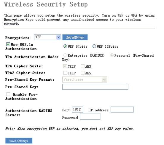
Ø
Authentication
RADIUS Server port
The service port of the external RADIUS server.
Ø
Authentication
RADIUS Server IP address
The IP address of external RADIUS server.
Ø
Authentication
RADIUS Server IP Password
The password
used by external RADIUS server.
For the WEP settings
please refer to section 4.3.3.2 WEP.
4.3.3.4.
WPA
Wi-Fi Protected Access (WPA) is an advanced security standard. You can use a pre-shared key to authenticate wireless stations and encrypt data during communication. It uses TKIP or CCMP (AES) to change the encryption key frequently. So the encryption key is not easy to be broken by hackers. This can improve security very much.
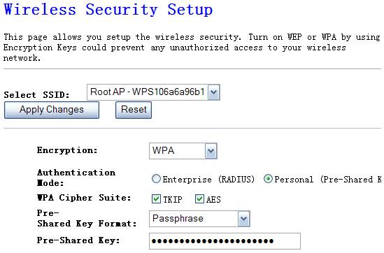
Figure 4‑12
Ø
WPA(TKIP)
TKIP can change the encryption key frequently to enhance the
wireless LAN security.
Ø
WPA(AES)
This uses CCMP protocol to change encryption key frequently. AES
can provide high level encryption to enhance the wireless LAN security.
Ø
Personal
(Pre-Shared Key)
You may select to select Passphrase (alphanumeric format) or
Hexadecimal Digits (in the “A-F”, “a-f” and “0
Ø
You can use an external RADIUS server to authenticate wireless
stations and provide the session key to encrypt data during communication. It
uses TKIP or CCMP(AES) to change the encryption key frequently. This can
improve security very much.
Ø
RADIUS Server
port
The service port of the external RADIUS server.
Ø
RADIUS Server IP
Address
The IP address of external RADIUS server.
Ø
RADIUS Server
Password
The password used by external RADIUS server.
4.3.3.5.
WPA2
If you want your wireless network more secure , you should select WPA2 instead of WPA. And the particular settings of WPA you can refer to WPA.
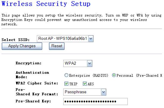
Figure 4‑13
4.3.3.6. WPA-Mixed
WPA/WPA2 can detect Wireless Client authentication
information, and automatically choose WPA or WPA2 mode to communicate with
client. Operation is the same as WPA or WPA2.
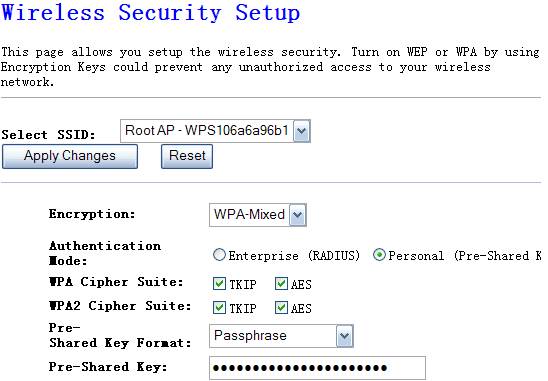
Figure 4‑14
This NW725P provides MAC Address Control,
which prevents the unauthorized MAC Addresses from accessing your wireless
network.
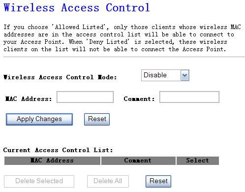
Figure 4‑15
Ø
Disable
Disable wireless access control
Ø
Allow listed
& Deny listed
Fill in the "MAC Address" and "Comment" of the
wireless station to be added and then click "Add". Then this wireless
station will be added into the "Current Access Control List" below.
If you find any issues before adding it and want to retype again. Just click
"delete" and both "MAC Address" and "Comment"
fields will be cleared.
Wireless Distribution System uses wireless
media to communicate with other APs, like the Ethernet does. To do this, you
must set these APs in the same channel and set MAC address of other APs which
you want to communicate with in the table and then enable the WDS.
Figure 4‑16
This
function provides tool to scan the wireless network. If any Access Point or
IBSS is found, you could choose to connect it manually when client mode is
enabled.
Figure 4‑17
Using the feature could let
your wireless client automatically synchronize its setting and connect to the
Access Point in a minute without any hassle.
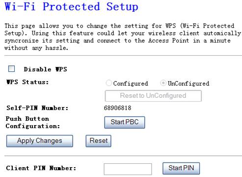
Figure 4‑18
4.3.7.1. Method 1 PIN Input Config (PIN)
1.
Input
the wireless NIC’s PIN Code into AP and click Start PIN on the AP-Router WPS config page
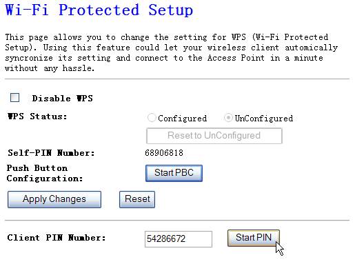
Figure 4‑19
2.
Click
Pin Input Config(PIN) on wireless
network adapter utility.
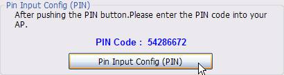
Figure 4‑20
3.
Select
one WPS AP which you want connect to and click Select button

Figure 4‑21
4.
Please
wait when the Figure
4‑22 pop-up appear, the secure connection between AP and
wireless NIC will be founded automatically.

Figure 4‑22
4.3.7.2. Method 2 Push Button
1.
Click
Push Button Config(PBC) on wireless
network adapter utility

Figure 4‑23
2.
Click
Start PBC on the AP-Router WPS
config page
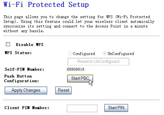
Figure 4‑24
3.
Please
wait when the Figure
4‑22 pop-up appear, the secure connection between AP and
wireless NIC will be founded automatically.
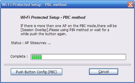
Figure 4‑25
Remark
If there is more than one AP on the PBC mode, there will be session overlap. Please using method 1 PIN Input Config(PIN) or wait for a while push the button again.
4.3.8. Wireless Schedule
This page allows you setup the wireless schedule rule.
Please do not forget to configure system time before enable this feature.
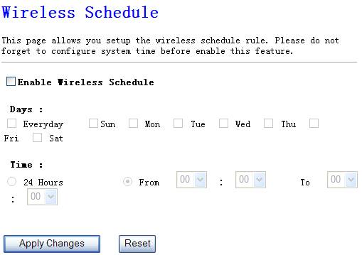
Figure 4‑26
4.4. TCP/IP Settings
4.4.1. LAN Interface
The
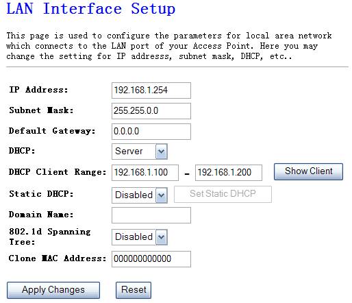
Figure 4‑27
Ø
IP Address
This
is the router’s LAN port IP address (Your LAN clients default gateway IP
address), the default is 192.168.1.1
Ø
Subnet Mask
Specify
a Subnet Mask for your LAN segment
Ø
Default Gateway
The
IP address of Default gateway you obtained after connect to the Internet, if
you haven’t connected to Internet yet, this field is blank.
Ø
DHCP Server
You
can enable or disable the DHCP server. By enabling the DHCP server the router
will automatically give your LAN clients an IP address. If the DHCP is selected
client, the router will get an IP address from the other DHCP Server
Ø
You
can select a particular IP address range for your DHCP server to issue IP
addresses to your LAN Clients.
Ø
Domain name
put into a name to mark your DHCP SERVER
Ø
802.1d Spanning
tree
You can enable or disable the Spanning tree for your
router
Ø
Clone MAC address
Replace the LAN MAC address with the MAC address of that
PC
4.4.2. WAN Interface
Configure
the parameters for Internet network which connects to the WAN port of your
Access Point. Here you may select access method to static IP, DHCP, PPPoE, PPTP
or L2TP by click the item value of WAN Access type.
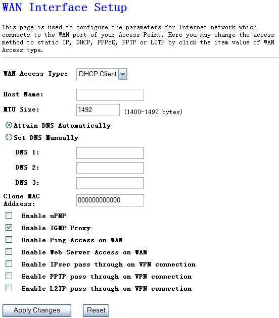
Figure 4‑28
Ø
Static IP address
Select Static IP if all the internet port’s IP information is provided by your ISP. You will need to enter the IP address, subnet mask, gateway address, and the DNS address provided to you by your ISP.
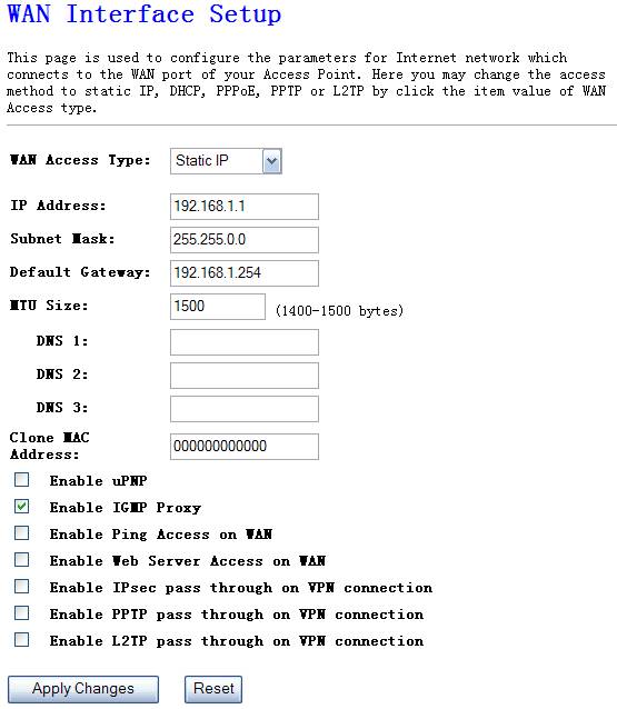
Figure 4‑29
Ø
DHCP Client
Select DHCP Client if Your ISP does not give you any IP number and uername&password to use, this option is commonly used for cable modem services.
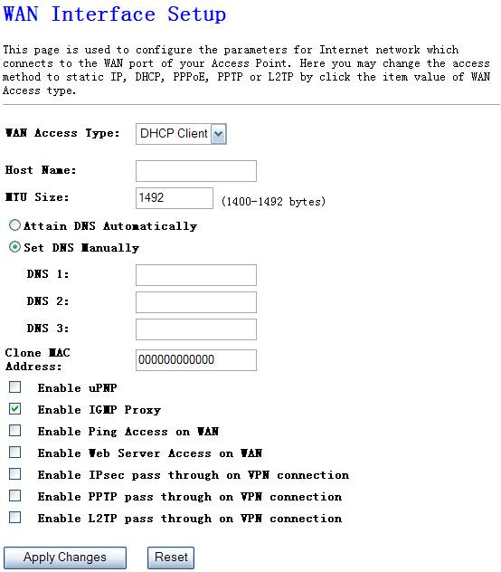
Figure 4‑30
Ø
PPPoE
Choose PPPoE(point to point over Ethernet) if Your ISP requires PPPoE connection, and you must enter the username and password which your ISP provide.
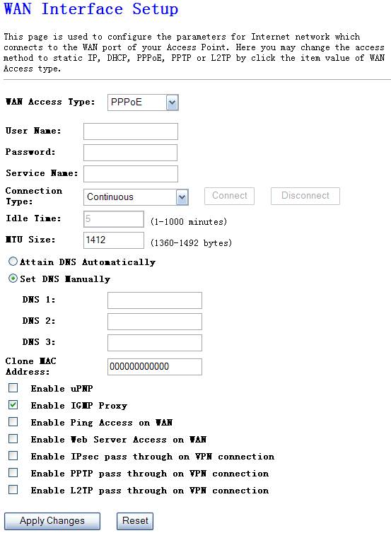
Figure 4‑31
Ø
PPTP
Your ISP requires you to use a PPTP connection. Your ISP will provide you with a username&password and server IP address. This option is typically used for DSL services.
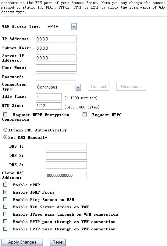
Figure 4‑32
Ø
L2TP
Your ISP requires you to use a L2TP connection. Your ISP will provide you with a username&password, IP address, subnet mask and IP address. This option is typically used for DSL services.
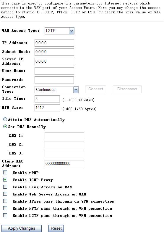
Figure 4‑33
4.5. Firewall
The Broadband router provides
extensive security protection by restricting connection parameters, thus
limiting the risk of hacker attack, and defending against a wide array of
common Internet attacks.
You can filter users by
enabling this function; thus unauthorized users can not access the network.
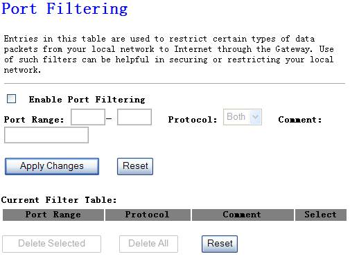
Figure 4‑34
Ø
Enable port filtering
Ø
Add ports you want to control
Ø
Protocol
Select the port number protocol type (TCP, UDP or both). If you
are unsure, then leave it to the default both protocol
Ø
Comment
The description of this setting
Click “Apply
Changess” at the bottom of the screen to save the above configurations
You can filter wired users by
enabling this function; thus unauthorized users can not access the network.
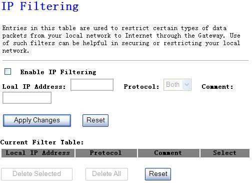
Figure 4‑35
Ø
Enable IP
Filtering
Enable IP filtering
Ø
Local IP Address
Add LAN IP address you want to control
Ø
Protocol
Select the port number protocol type (TCP, UDP or both). If you
are unsure, then leave it to the default both protocol
Ø
Comment
The description of this setting
Click “Apply
Changess” at the bottom of the screen to save the above configurations
You can filter wired users by
enabling this function; thus unauthorized users can not access the network.

Figure 4‑36
Ø
Enable MAC
Filtering
Enable MAC filtering
Ø
MAC Address
Add MAC address you want to control
Ø
Comment
The description of this setting
Click “Apply
Changess” at the bottom of the screen to save the above configurations
This function will allow you to open a single or a
range of ports.
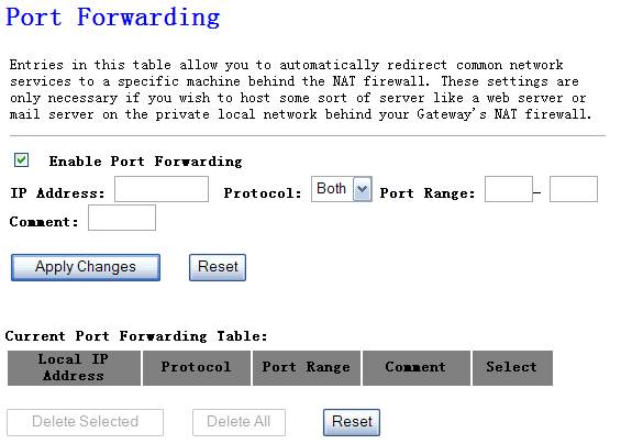
Figure 4‑37
Ø IP Address
Enter the IP address of the computer on your local
network that you want to allow the incoming service to.
Ø Protocol
Select TCP or UDP which protocol the incoming service
use.
Ø
Enter the port or port range that you want to open.
Example: 23, 1444, 23-68
Ø Comment
Name the rule, description of the rule.
URL filter is used to deny
LAN users from accessing the internet. Block those URLs which contain keywords
listed below.
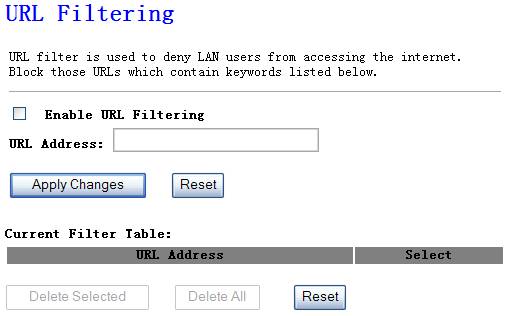
Figure 4‑38
Fill in “URL Address” and then click “Apply Changes”. You can enter the full
URL address or the keyword of the web site you want to block. If you find any
typo before adding it and want to retype again, just click "Delete"
and the field will be cleared.
If you have a local client PC
that cannot run an Internet application (e.g. Games) properly from behind the
NAT firewall, then you can open the client up to unrestricted two-way Internet
access by defining a DMZ Host. The DMZ function allows you to re-direct all
packets going to your WAN port IP address to a particular IP address in your
LAN. The difference between the virtual server and the DMZ function is that the
virtual server re-directs a particular service/Internet application to a
particular LAN client/server, whereas DMZ re-directs all packets (regardless of
services) going to your WAN IP address to a particular LAN client/server.
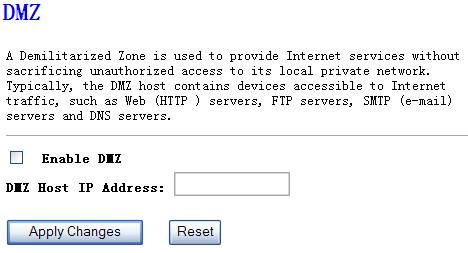
Figure 4‑39
4.6.
QOS
The QOS
Engine option helps improve your network gaming performance by prioritizing
applications. By default the QOS Engine settings are disabled and application
priotity is not classified aromatically.
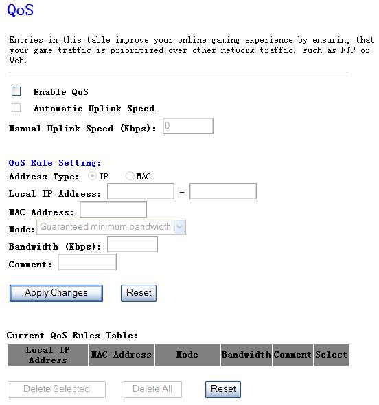
Figure 4‑40
Ø
Enable QOS
This option
is disabled by default. Enable this option for better performance and
experience with online games and other interactive applications, such as WEB.
Ø
Automatic Uplink
This option
is disabled by default when the QOS is enabled. Enabled this option will allow
your router to automatically determine the uplink speed of your internet
connection.
Ø
Manual Uplink
Speed
You can set
the uplink speed manually by this option.
Ø
QOS Rule Setting
l
Address Type
Select IP or
MAC which you want the QOS rule based on.
l
Local IP Address
Enter a
single IP or IP range
l
MAC Address
Enter the local
PC’s MAC address which you want to do limiting.
l
Mode
There two
modes of the QOS rules, one is Guarantee minimum bandwidth, the other is Restricted
maximum bandwidth.
l
Bandwidth
Enter the
bandwidth value of the QOS rule, for example 128
l
Comment
Enter the name of the QOS rule.
4.7. Management
The Status section allows you to monitor the current
status of your router, including uptime, firmware version, wireless
configuration, TCP/IP configuration and WAN configuration
Figure 4‑41
Here you can view the amount of packets that pass through
the NW725P on both WAN and LAN. The traffic
counter will reset if the device is rebooted.
Figure 4‑42
DDNS allows you to map the
static domain name to a dynamic IP address. You must get an account, password
and your static domain name from the DDNS service providers. This router
supports DynDNS, TZO and other common DDNS service providers.
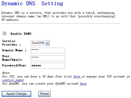
Figure 4‑43
Ø
Enable
DDNS
Enable/Disable the DDNS function of this router
Ø
Service
Provider
Select a DDNS service provider
Ø
Domain
Name
Your static domain name that use DDNS
Ø
User
Name/Email
The account that your DDNS service provider assigned to you
Ø
Password/Key
The password you set for the DDNS service account above
The time zone setting option allow you to configure ,
update and maintain the current time on the internal system clock. From this
section you set the time zone that you are in and set the time server. Daylight
saving can also be configured to automatically adjust the time when needed.
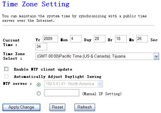
Figure 4‑44
Ø
Current time
You can set the NW725P time by this section by yourself.
Ø
Time Zone Select
Select time zone from the
dropdown menu.
Ø
Enable NTP client
update
NTP is a short for network
time protocol. NTP synchronizes computer clock times in a network of computers.
Check this box to use a NTP server in the internet but not local server.
Ø
Automatically
Adjust Daylight Saving
To this section, select
disable or enable.
Ø
NTP server
Select a NTP server from the drop-down menu.
A "denial-of-service" (DoS) attack is
characterized by an explicit attempt by hackers to prevent legitimate users of
a service from using that service.
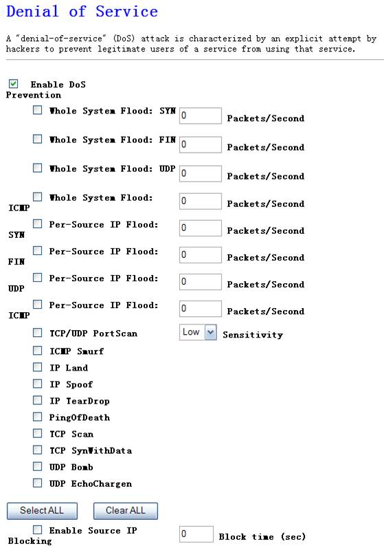
Figure 4‑45
This page shows the current system log of the Broadband router. It displays any event occurred after system start up, including view all information of system, wireless information, Dos attack information and so on.
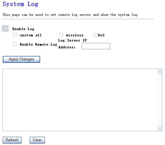
Figure 4‑46
Ø Enable Log
Enable system log, including system all, wireless and
Dos
Ø Enable Remote Log
The system keeps a running log of events and activities occurring on the router. If you want the router send these log to a server, enable this section and enter the server’s IP address.
This page allows you to upgrade the router’s firmware
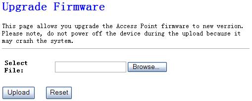
Figure 4‑47
This tool allows you to
upgrade the Broadband router’s system firmware. To upgrade the firmware of your
Broadband router, you need to download the firmware file to your local hard
disk, and enter that file name and path in the appropriate field on this page.
You can also use the Browse button to find the firmware file on your PC.
Once you’ve selected the new firmware file, click “Upload” at the bottom of the screen to start the upgrade process. (You may have to wait a few minutes for the upgrade to complete). Once the upgrade is complete you can start using the router.
This page allows you save
current settings to a file or reload the settings from the file which was saved
previously. Besides, you could reset the current configuration to factory
default
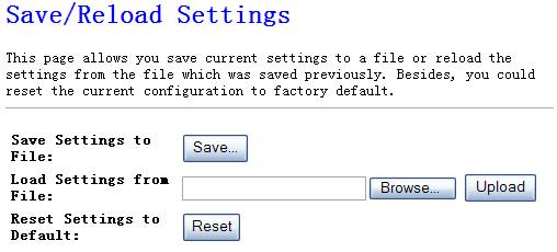
Figure 4‑48
This page is used to set the
account to access the web server of Access Point. Empty user name and password
will disable the protection.
Figure 4‑49
5. FAQ
1. I cannot access the Web-based
Configuration Utility from the Ethernet computer used to configure the router.
l Check that the LAN LED is on. If
the LED is not on, verify that the cable for the LAN connection is firmly
connected.
l Check whether the computer
resides on the same subnet with the router’s LAN IP address.
l If the computer acts as a DHCP
client, check whether the computer has been assigned an IP address from the
DHCP server. If not, you will need to renew the IP address.
l Use the ping command to ping the
router’s LAN IP address to verify the connection.
l Make sure your browser is not
configured to use a proxy server.
l Check that the IP address you
entered is correct. If the router’s LAN IP address has been changed, you should
enter the reassigned IP address instead.
2. I forget Password (Reset the
Router without Login)
l
Plug out the
power of the Router.
l
Use a pencil to
press and hold the default button on the back panel of the Router. Then plug in
the power of the Router.
l
Press and hold
the default button wait for a few seconds until the CPU LED indicator stays
green.
l
Reboot the AP.
l
After the above
those steps, the manufacture’s parameters will be restored in the Router. The
default password is guest.
3. I have some problems related
to Connection with Cable Modem
Please follow
the following steps to check the problems:
l Check whether the DSL modem works well
or the signal is stable. Normally there will be some indicator lights on the
modem, users can check whether the signal is ok or the modem works well from
those lights. If not, please contact the ISP.
l Check the front panel of the Router,
there are also some indicator lights there. When the physical connection is
correct, the Power light and the CPU light should be solid; the WAN light
should be blinking. If you use your computer, the corresponding LAN port light
should be blinking too. If not, please check whether the cables work or not.
l Repeat the steps in WAN Setup Connect
with Internet through DSL Modem.
4. I can browse the router’s
Web-based Configuration Utility but cannot access the Internet.
l Check if the WAN LED is ON. If
not, verify that the physical connection between the router and the DSL/Cable
modem is firmly connected. Also ensure the DSL/Cable modem is working properly.
l If WAN LED is ON, open the System
Overview page of the Web configuration utility and check the status group to
see if the router’ s WAN port has successfully obtained an IP address.
l Make sure you are using the
correction method (Dynamic IP Address, PPPoE, or Static IP) as required by the
ISP. Also ensure you have entered the correct settings provided by the ISP.
l For cable users, if your ISP requires a
registered Ethernet card MAC address, make sure you have cloned the network
adapter’ s MAC address to the WAN port of the router. (See the MAC Address field
in WAN Setup.)
5. My wireless client cannot
communicate with another Ethernet computer.
l Ensure the wireless adapter
functions properly. You may open the Device Manager in Windows to see if the
adapter is properly installed.
l Make sure the wireless client
uses the same SSID and security settings (if enabled) as the NW725P.
l Ensure that the wireless
adapter’s TCP/IP settings are correct as required by your network
administrator.
l If you are using a 802.11b wireless
adapter, and check that the
l Use the ping command to verify
that the wireless client is able to communicate with the router’s LAN port and
with the remote computer. If the wireless client can successfully ping the
router’ s LAN port but fails to ping the remote computer, then verify the
TCP/IP settings of the remote computer.